
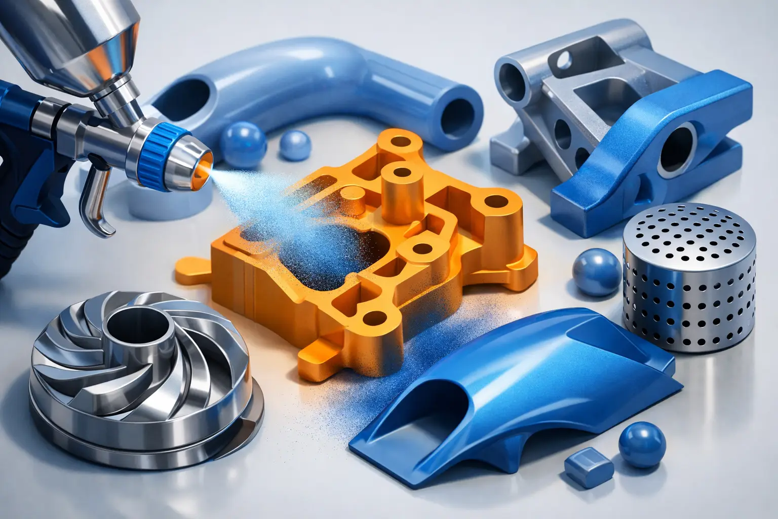
A coating can perform perfectly on a flat witness coupon and still fail on the component that matters. Deep bores, sharp transitions, blind holes, undercuts, fine threads and densely assembled electronic modules all change how precursor molecules, plasma species or deposited atoms reach a surface. Knowing how to coat complex geometries therefore starts with a practical question: which functional surfaces must receive a defined coating thickness, and which surfaces must remain free of material?
For technically demanding components, geometry is not a secondary consideration. It determines process selection, fixture design, loading density, masking strategy, inspection method and ultimately production capability. A successful solution combines material science with a precise understanding of the part, its function and its manufacturing environment.
Why complex geometries challenge coating processes
Every deposition technology has a characteristic line of sight, transport mechanism and reaction behaviour. Conventional spray or dip processes may struggle to reach recessed areas evenly. Physical vapour deposition, or PVD, generally follows a directional particle path, making shadowed surfaces particularly demanding unless the process and part movement are engineered accordingly.
Vacuum-based conformal deposition processes behave differently. Parylene, for example, is deposited from a gaseous monomer and can coat exposed surfaces within complex three-dimensional structures with exceptional uniformity. This makes it particularly valuable for fine electronic assemblies, medical devices, sensors, springs, porous structures and components with long, narrow features. However, even a highly conformal process does not remove all engineering constraints. Trapped volumes, inaccessible surfaces, outgassing materials and tightly contacting interfaces still require assessment.
Plasma and CVD processes introduce further variables. Their performance depends on gas flow, pressure, plasma distribution, precursor chemistry, surface activation and the interaction between the process environment and component geometry. The right answer is therefore rarely a generic coating specification. It is a defined process window for a specific component family.
How to coat complex geometries: start with functional analysis
The most reliable projects begin before the coating chamber. First, define the coating function in measurable terms. Corrosion protection, dielectric insulation, low friction, barrier performance, biocompatibility, chemical resistance and optical behaviour each create different requirements for thickness, adhesion, pinhole tolerance and surface coverage.
A medical guidewire component may need a thin, continuous layer that preserves dimensional tolerances and supports biocompatibility. An electronics assembly may require dielectric protection across solder joints, sharp edges and areas beneath component overhangs. A precision mechanical part may need controlled friction or wear resistance only on selected contact zones. These are not simply different applications. They are different coating tasks.
The design review should identify critical geometrical features: aspect ratios of holes and channels, recess depth, local edge radii, overlapping components, welded seams, mating surfaces and areas that may trap process residues. CAD data is useful, but it should be complemented by physical samples. Manufacturing tolerances, burrs, surface roughness and assembly gaps often influence coating behaviour more than the nominal geometry suggests.
Specify thickness where it matters
A single nominal thickness is often insufficient for a complex part. Instead, specify the minimum thickness at critical locations and the permitted maximum on tolerance-sensitive areas. This distinction is especially relevant for thin films used in electrical insulation or fluid barriers, where local weak points can determine field performance.
It also prevents unnecessary overcoating. More material is not automatically better: excess thickness can alter fits, reduce flexibility, bridge fine features or create stress in the coating system. Process development should target functional performance with the lowest technically suitable material build-up.
Match deposition physics to the geometry
Process selection must follow the transport behaviour of the coating technology, not a preference for a familiar method.
Parylene is frequently selected where conformality is the defining requirement. Because deposition occurs through molecular transport in vacuum, the coating can cover external contours, internal cavities and intricate assemblies without the pooling or edge thinning associated with many liquid-applied systems. Its value is particularly clear when a component contains a combination of sharp edges, fine gaps and non-line-of-sight surfaces.
PVD coatings offer high-performance functional layers, including hard, low-friction and decorative systems, but their directional nature requires careful management of shadowing. Rotating fixtures, planetary movement, target arrangement and multiple deposition angles can improve coverage. Whether this is sufficient depends on the geometry and on how critical the shadowed areas are to the component’s function.
Plasma treatment is often not the final coating step but is decisive for preparation. It can remove organic contamination, activate low-energy polymer surfaces and improve adhesion in regions that would otherwise create coating discontinuities. For components with narrow channels or internal features, plasma uniformity must be verified rather than assumed.
Hybrid systems can be appropriate when one technology supplies adhesion or surface activation and another provides the functional layer. For example, a plasma pre-treatment followed by a conformal polymer coating may achieve reliable coverage and adhesion on challenging substrates. The technical benefit must justify the added process complexity, validation effort and cycle time.
Surface preparation is part of the coating system
Complex shapes are difficult to clean consistently. Fingerprints in a recess, machining lubricant in a blind bore or flux residue beneath an electronic component can compromise adhesion and barrier performance despite an otherwise well-controlled deposition process.
Cleaning must be selected for both the contamination and the geometry. A method that cleans an accessible external face may not adequately remove residues from a capillary-like channel. Likewise, cleaning chemistry must be compatible with the substrate, adhesives, elastomers and assembled electronics. Drying is equally significant: retained moisture or solvents can outgas in vacuum, affect deposition conditions and introduce local defects.
For regulated applications, preparation needs a documented and reproducible route. This includes defined handling, cleaning media, drying parameters, storage time before coating and loading instructions. Certified processes are built from controlled details, particularly where component geometry makes visual verification difficult.
Fixture design determines repeatability
Fixtures are often treated as production hardware rather than process engineering. For complex geometries, that is a costly mistake. The fixture determines orientation, spacing, exposure, thermal contact, electrical isolation where relevant, and whether surfaces are blocked or exposed during deposition.
A well-designed fixture holds components securely without damaging sensitive surfaces or creating avoidable masking marks. It separates parts sufficiently to prevent mutual shadowing and allows process media to reach critical features. In PVD systems, movement may be integral to uniformity. In conformal vacuum coating, fixture orientation can influence trapped volumes, handling risk and the ability to coat internal structures consistently.
Loading density must be qualified as well. A process that produces excellent results with ten development parts can behave differently with a full industrial load. Parts can shield one another, alter gas flow patterns or increase total surface area beyond the established process window. Scale-up should therefore be planned from the initial feasibility phase, not after product approval.
Use masking only when it serves a defined function
Selective coating adds another layer of geometrical complexity. Connectors, electrical contact pads, bonding areas, optical windows and tight mechanical interfaces may need to remain uncoated. The masking method must create a repeatable boundary while resisting process conditions and avoiding residue.
Mechanical masks can provide sharp boundaries and are suitable where the part design permits reliable placement. Temporary materials may be effective for selected processes but require validation for contamination, removal and edge definition. In some cases, product redesign is the better solution: a small change to a contact land, sealing face or assembly sequence may eliminate a difficult masking operation entirely.
The trade-off is clear. More selective coverage can improve component function, but it increases handling, inspection requirements and the risk of variation. The best approach is the simplest one that satisfies the functional specification.
Verify coverage at the critical locations
Complex geometries demand a verification strategy that follows risk, not convenience. Measuring thickness only on an accessible outer face says little about a blind recess or a shielded internal feature.
Depending on the material and requirement, verification may combine witness samples, cross-sections, microscopy, optical methods, electrical testing, leak testing, adhesion assessment or functional environmental testing. Witness coupons remain useful for monitoring the process, but they do not replace evidence from representative component locations.
A sensible qualification programme deliberately includes worst-case geometries: the deepest bore, tightest gap, sharpest edge, most crowded assembly and maximum production load. Where destructive analysis is necessary, it should be performed early enough to establish confidence before routine production begins. Once the critical relationships between geometry, loading and coating performance are understood, process control becomes more efficient and more defensible.
Build coating capability around the real production case
For prototype quantities, specialist contract coating can provide fast access to process expertise and development equipment. For serial production, the decision may shift towards a tailored coating system integrated with cleaning, handling, masking, curing and quality control. Neither route is universally superior.
The appropriate model depends on annual volume, component variability, confidentiality, regulatory documentation, required response time and the value of internal process control. NTTF Coatings develops both application-specific coating processes and customised equipment concepts because the coating chamber alone is rarely the complete manufacturing answer.
The most effective route is to involve coating engineering while the component design is still open to change. A chamfer instead of a sharp re-entrant corner, a revised assembly sequence or a small adjustment to a hole diameter can make the difference between a technically possible coating and a stable, economical production process.
Complex geometry is not a reason to accept uncertain coverage. It is a reason to define the functional surfaces precisely, select the process according to deposition physics and qualify the entire chain from cleaning to inspection. When those decisions are made early, intricate components can receive high-performance coatings with the consistency that demanding industrial and regulated applications require.
