
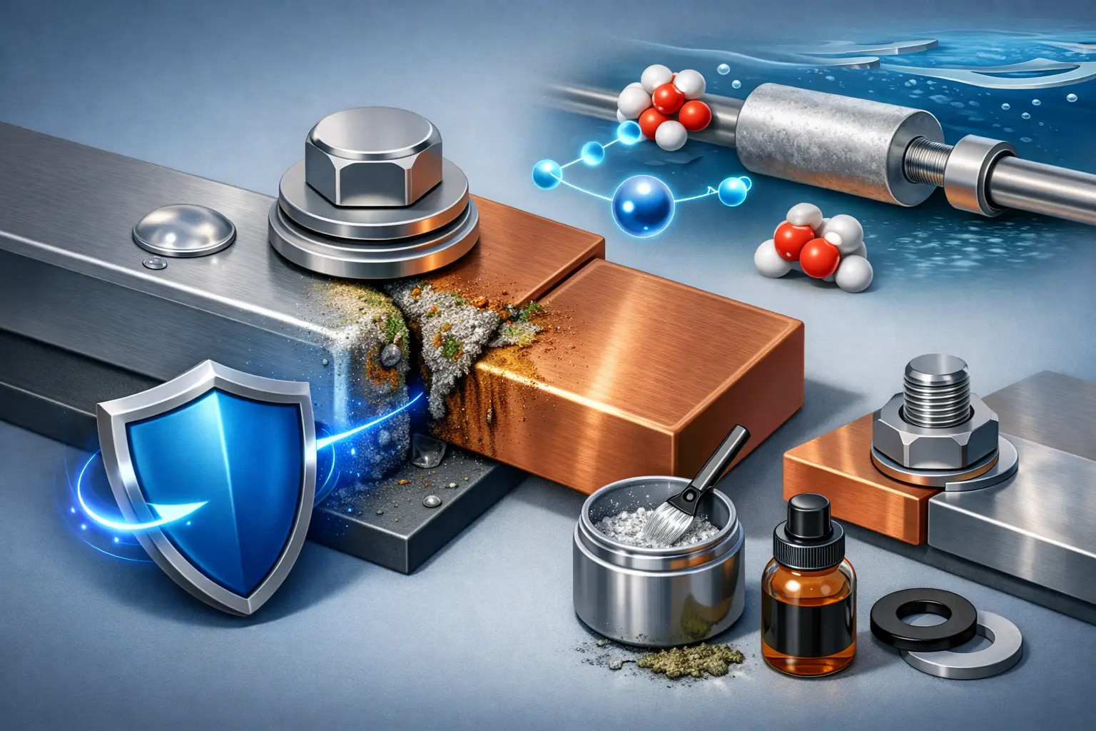
A stainless-steel fastener in an aluminium housing may look like a minor assembly choice. In a wet, salt-laden or chemically active environment, it can become the starting point for rapid localised attack on the aluminium. Understanding how to prevent galvanic corrosion therefore begins before a component reaches production: at material selection, interface design and validation under realistic service conditions.
Galvanic corrosion is rarely caused by one poor decision alone. It usually results from a conductive path between dissimilar metals, an electrolyte such as condensation or process fluid, and a design that allows moisture to remain at the joint. Effective prevention removes one or more of these conditions in a controlled, reproducible way.
Why galvanic corrosion develops at metal interfaces
When two electrically connected metals have different electrochemical potentials and are exposed to an electrolyte, they form a galvanic cell. The more active metal becomes the anode and corrodes preferentially. The more noble metal acts as the cathode and is protected at the anode’s expense.
The severity depends on more than the position of each metal in a galvanic series. Electrolyte conductivity, temperature, oxygen availability, crevices, surface condition and the relative exposed areas all influence the corrosion rate. A small anodic aluminium area coupled to a large cathodic stainless-steel surface is particularly unfavourable, because corrosion current is concentrated over a limited area.
This is why material pairings that perform acceptably in a dry indoor instrument can fail in coastal infrastructure, vehicles subjected to de-icing salts, marine assemblies or medical devices exposed to cleaning and sterilisation media. The relevant question is not whether two metals can touch in theory, but whether they can remain electrically and chemically stable throughout the intended operating life.
How to prevent galvanic corrosion at the design stage
The most efficient controls are designed into the product architecture. Retrofitting coatings or seals after a failure investigation is often possible, but it may introduce qualification effort, dimensional compromises and higher process costs.
Select compatible material combinations
Where practical, use metals close together in galvanic potential for the actual service environment. Similar aluminium alloys, compatible stainless-steel grades or matched titanium components may reduce the driving force compared with a strongly dissimilar pairing.
This principle has limits. Mechanical strength, weight, electrical conductivity, magnetic behaviour, biocompatibility and cost can make a single-metal construction unsuitable. In these cases, dissimilar materials can still be used reliably, provided that their interface is deliberately isolated and protected.
Material data should be assessed with the intended electrolyte in mind. Galvanic behaviour in aerated seawater, for example, cannot simply be transferred to low-conductivity condensate, process chemicals or physiological fluids. For regulated applications, this assessment should be documented alongside the relevant material specifications and cleaning conditions.
Control the anode-to-cathode area ratio
If dissimilar materials cannot be avoided, avoid a small anode coupled to a large cathode. A larger area of the less noble metal can distribute corrosion current more favourably, while a small cathodic area limits the reaction it can support.
Fasteners deserve particular attention. A noble fastener installed in a less noble structural material often creates a geometrically unfavourable couple at precisely the location where crevices, damaged coatings and moisture retention are likely. Selecting compatible fastener materials or introducing a defined insulating interface is usually more reliable than relying on sealant alone.
Electrically isolate the joint
Electrical isolation breaks the galvanic circuit. Non-conductive washers, bushings, sleeves, gaskets and engineered adhesive layers can separate fasteners, flanges, housings and inserts. The selected material must maintain dielectric performance under assembly loads, vibration, thermal cycling and exposure to fluids.
Isolation is only effective when it is complete. A coated washer offers little protection if a screw thread, burr, conductive debris or a compressed edge provides an alternative metal-to-metal path. Assembly instructions, torque windows and inspection criteria should therefore be defined as part of the corrosion-control concept.
Design out retained electrolytes
Water trapped in a lap joint, under a flange or beneath a poorly drained enclosure can sustain corrosion long after external surfaces appear dry. Drainage paths, ventilation, joint orientation and avoidance of narrow stagnant crevices are functional design features, not cosmetic details.
Where sealing is necessary, specify materials that remain stable against the expected medium and temperature range. A seal that shrinks, cracks or loses adhesion may create a concentrated electrolyte pathway at the most sensitive interface. For outdoor and mobility applications, consider repeated wet-dry cycles and salt contamination rather than immersion exposure alone.
Protective coatings: isolate the surface, protect the interface
Coatings are a central tool for preventing galvanic corrosion, but their protection mechanism must match the component geometry and failure risk. The objective may be to electrically separate metals, exclude electrolytes, reduce permeation or protect a local contact zone without changing critical tolerances.
Conventional paint systems, anodising, conversion treatments and metallic coatings can be appropriate depending on the substrate and application. Their limitations should be considered early. Porosity, edge coverage, damage during assembly and local masking requirements can determine whether a nominally protective system remains protective in service.
Thin-film and polymer barrier coatings provide further options where complex geometries, small features or functional surfaces need controlled protection. Parylene, deposited from the vapour phase, forms a conformal dielectric barrier around edges, recesses and fine structures that are difficult to cover uniformly by liquid processes. Its suitability depends on adhesion, film thickness, environmental exposure, intended electrical function and the need to mask contact areas.
PVD, CVD and hybrid coatings can also contribute where wear resistance, low friction, chemical stability or defined electrical properties are required alongside corrosion protection. A hard thin film is not automatically an effective galvanic barrier: pinholes, conductive coating compositions, insufficient edge coverage and damage at mating interfaces must be assessed. The coating system should be engineered as part of the full assembly, not selected from a data sheet in isolation.
For demanding projects, NTTF Coatings develops application-specific coating concepts and process windows that account for substrate preparation, adhesion, geometry, masking and reproducibility. This is particularly relevant where corrosion protection must coexist with medical, electronic or precision-mechanical requirements.
Prepare surfaces and assembly processes with discipline
Surface preparation strongly influences whether a protective layer performs as designed. Oils, particles, oxides, moisture and residues from machining or cleaning can weaken adhesion and create local defects. Define cleaning, activation and handling steps according to the substrate and coating process, then maintain them under controlled production conditions.
Mechanical assembly can compromise an otherwise effective surface treatment. Thread engagement, press fits, rivets, clips and sharp edges can crack or abrade coatings. In such cases, the assembly sequence may need adjustment: coat after joining where feasible, protect interfaces with compatible sleeves, or create dedicated uncoated contact regions that are separately sealed and isolated.
Process validation should include representative parts, not only flat witness coupons. Corners, blind holes, threaded areas, narrow gaps and transitions between materials are the locations most likely to reveal insufficient coverage or unexpected electrical bridging.
Validate against the real service environment
Salt-spray testing is useful, but it is not a universal predictor of galvanic performance. A component exposed to high humidity, condensation, intermittent chemical cleaning, thermal cycling or vibration may need a test programme that reproduces these combined stresses. The goal is to understand the failure mechanism, not simply to achieve a test duration.
A credible validation plan may combine electrochemical assessment, humidity or cyclic corrosion exposure, adhesion testing, electrical insulation measurements and post-test microscopy. For safety-critical or regulated products, define acceptance limits in advance: permissible corrosion area, coating defects, insulation resistance, torque retention or functional performance.
Inspection must continue into series production. Coating thickness, coverage, cure or deposition parameters, cleanliness and masking quality should be monitored using traceable methods. Reproducibility is especially critical where a microscopic defect can initiate corrosion beneath an otherwise intact barrier.
When electrical bonding is required
Some assemblies require deliberate electrical continuity for grounding, electromagnetic compatibility or signal integrity. In these cases, complete isolation is not an option. Prevention shifts towards minimising exposed galvanic couples, controlling moisture ingress and using localised, stable contact designs.
Keep the bonded area small and well defined, protect adjacent surfaces, and avoid conductive pathways that collect electrolyte. Depending on the system, a compatible interlayer, conductive coating or controlled sealing strategy may be appropriate. The trade-off must be explicit: improving electrical contact can increase corrosion risk unless the environmental barrier is equally well engineered.
The most reliable corrosion strategy is usually the one embedded in the drawing, material specification and assembly process from the outset. When the interface is treated as an electrochemical system rather than a simple mechanical joint, service life becomes predictable and protection can be verified before field failures dictate the next design change.
