
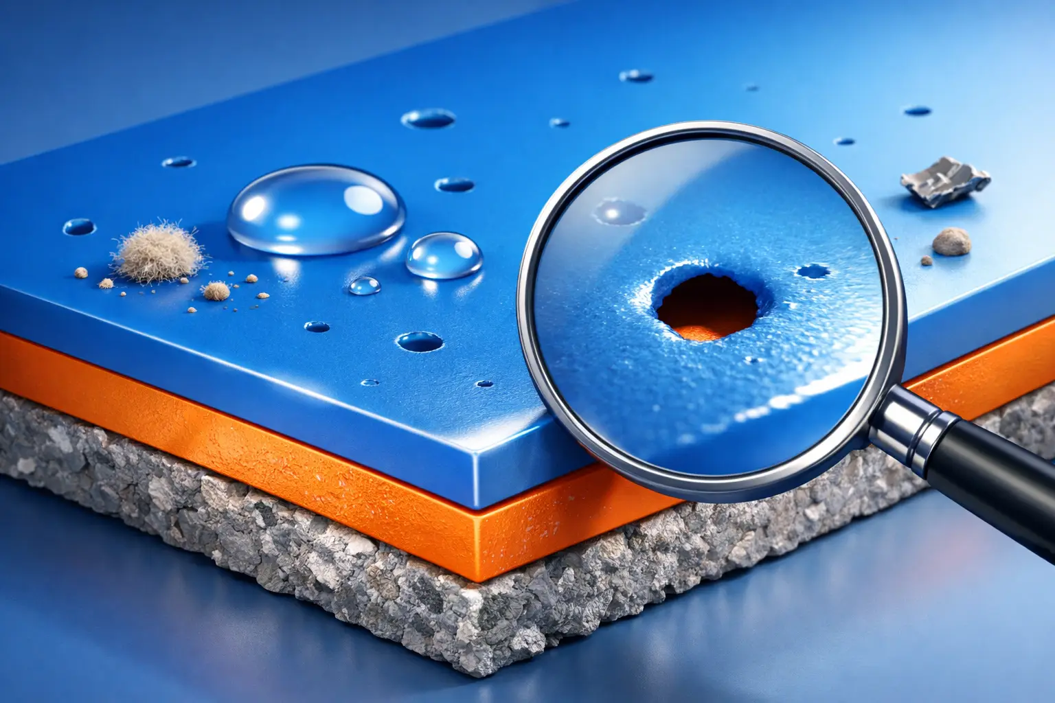
A pinhole can be only a few micrometres wide, yet it may determine whether a coated component passes a corrosion test, maintains electrical insulation or protects a sensitive medical device. When engineers ask what causes thin film pinholes, the useful answer is rarely a single parameter. Pinholes are usually the visible outcome of an interaction between substrate condition, component geometry, material behaviour and process control.
For high-performance coatings, a visually acceptable surface is not enough. A discontinuity that reaches the substrate can become a pathway for moisture, ions, process media or electrical leakage. The right corrective action therefore starts by distinguishing the defect mechanism rather than simply increasing coating thickness.
What causes thin film pinholes?
Thin film pinholes are local discontinuities in a coating layer. They may be open pores, crater-like depressions, uncoated points above particles, or defects that form after deposition through shrinkage or mechanical damage. Their appearance can be similar under low magnification, while their root causes – and their consequences – differ substantially.
In liquid-applied systems, pinholes often arise when entrapped air, solvent vapour or substrate emissions break through a wet film. In vacuum-based processes such as PVD, CVD or Parylene deposition, they are more often associated with particles, inadequate surface preparation, shadowing, volatile contamination or insufficiently controlled deposition conditions. Plasma pretreatment can improve surface activation and cleaning, but it cannot compensate for every geometric or material-related limitation.
The critical question is whether the feature is generated before coating, during film formation, or after the layer has been deposited. This determines where investigation should begin.
The substrate is often the first source of the defect
Particles, residues and surface contamination
Dust, machining debris, polishing compounds, fingerprints, release agents and silicone-containing residues can prevent local film formation or create weakly bonded areas. A particle on the surface may be coated initially, then detach during handling or cleaning. What remains is a circular void that can resemble a deposition failure.
Contamination is especially significant for parts with complex supply chains. A component may arrive nominally clean but retain residues from forming lubricants, ultrasonic cleaning chemistry, packaging or previous handling steps. Even low surface concentrations can alter wetting or outgas under vacuum.
Cleaning must therefore be matched to the material and its prior processing. The objective is not simply a visually clean component, but a stable, reproducible surface with controlled surface energy and minimal volatile residue. For critical applications, incoming cleanliness criteria and traceable handling conditions are as relevant as the coating recipe itself.
Porosity, roughness and hidden cavities
Cast metals, sintered materials, fibre-reinforced polymers, additive-manufactured components and some ceramics may contain pores or cavities that act as defect initiators. A coating can bridge the opening of a pore without sealing it fully. Under thermal cycling, vacuum exposure or fluid contact, trapped gas or moisture can escape and disrupt the film.
Surface roughness is not automatically detrimental. Some roughness profiles improve mechanical anchoring, while sharp peaks and deep valleys can impair local coverage. The limiting factor is the relationship between feature size, coating thickness and deposition directionality. A layer that performs well on a polished planar coupon may not produce the same coverage on a textured production component.
Outgassing from the base material
Polymers, elastomers, adhesives, potting compounds and absorbed moisture can release volatile species during evacuation, heating or deposition. This outgassing can create local pressure disturbances, interfere with film growth or produce blister-like defects. Material batches, storage humidity and curing history may all influence the result.
Pre-baking, vacuum conditioning or an adapted plasma process can reduce this risk. However, the temperature window must remain compatible with the component, adhesives, electronics and dimensional tolerances. More heat is not automatically a better solution.
Film formation can turn minor variation into pinholes
Insufficient wetting and dewetting
For wet coatings, poor wetting is a common route to crater formation and pinholes. If the coating liquid retracts from a locally low-energy area, it leaves an exposed point or a very thin region. Silicone contamination is a particularly frequent cause, but incompatible additives, excessive surface treatment delay and uneven substrate energy can produce similar behaviour.
The remedy may involve plasma activation, revised cleaning, changes to viscosity or application parameters, and stricter controls over compatible materials in the production area. It depends on the coating chemistry: a surface treatment that improves adhesion for one system can be unsuitable for another.
Entrapped air, solvent and volatile by-products
Air can be introduced during mixing, pumping, spraying or application onto complex geometries. As the film levels or cures, bubbles rise and burst, leaving pinholes. Rapid solvent evaporation can create the same effect, particularly when a thick wet layer skins over before underlying volatiles can escape.
The balance between viscosity, layer thickness, flash-off time, temperature and cure profile is therefore decisive. Faster throughput can increase defect risk if it shortens the time needed for levelling and controlled degassing. In industrial production, this is a process-capability issue rather than an isolated operator error.
Particle generation inside the process
Not every particle originates from the customer component. Fixture wear, chamber residues, damaged masking materials, inadequate maintenance or cross-contamination from previous runs can introduce particles during deposition. In vacuum equipment, loose deposits on shields or chamber walls may become a recurring defect source.
A cleanroom classification alone does not guarantee a particle-controlled process. The relevant measures include chamber design, loading concept, fixture maintenance, cleaning validation and the discipline of change control. Customised equipment can be designed to reduce particle traps and make critical surfaces easier to access and clean.
Geometry and deposition physics matter
Thin films do not cover every surface feature equally. Directional processes may produce shadowing behind edges, within deep recesses, under overhangs or between closely spaced elements. As a result, an apparent pinhole may actually be a coverage limitation at a local geometric feature.
Parylene is valued for conformal deposition and can provide excellent coverage on intricate geometries. Even so, masking boundaries, very narrow gaps, enclosed volumes, surface contamination and substrate outgassing still require careful process development. PVD processes can offer highly functional layers, but their line-of-sight characteristics demand particular attention to component orientation, rotation and fixture design.
Thickness also involves a trade-off. Increasing it may reduce the probability that isolated defects penetrate the full layer, but it can add stress, alter dimensions, affect flexibility or extend cycle time. The appropriate thickness is determined by the barrier requirement, geometry, material pairings and intended service environment.
Pinholes may emerge after deposition
A film can leave the coating chamber intact and develop defects later. Internal stress, thermal expansion mismatch, aggressive cleaning media, bending, abrasion or sterilisation cycles may open microcracks or weaken areas around inclusions. In this case, the visible discontinuity is a reliability symptom rather than an as-deposited defect.
This distinction matters for qualification. Optical inspection identifies many surface defects, but it may not reveal sub-surface voids or early-stage adhesion failure. Depending on the application, meaningful evaluation can include microscopy, thickness mapping, electrical testing, corrosion exposure, environmental cycling and adhesion assessment. The test method should reflect the actual failure mode: a decorative requirement is assessed differently from an insulation barrier on high-density electronics.
A structured route to prevention
Pinholes are best reduced through a controlled development loop. First, establish the defect morphology and location with suitable microscopy. Next, compare defective and defect-free parts across material lot, cleaning route, handling history, fixture position and process data. This often reveals whether the source follows the component, the chamber position or a particular process step.
Process changes should then be tested in a defined sequence. Altering cleaning, pre-treatment, loading configuration, deposition conditions and post-treatment simultaneously makes root-cause identification difficult. A designed trial plan produces more reliable knowledge and supports later scale-up.
For regulated or safety-critical products, acceptance criteria should be defined before series production. They need to specify not only cosmetic appearance, but the permitted size, frequency and location of discontinuities in relation to function. A pinhole in a non-critical exterior area is not equivalent to one at an electrical clearance point, a fluid-contact surface or a corrosion-sensitive edge.
From defect finding to process capability
The most effective response to thin film pinholes is not a generic adjustment to coating time or temperature. It is a component-specific process strategy that links material selection, surface preparation, deposition physics, equipment configuration and verification methods.
For demanding applications, early feasibility work pays for itself by exposing geometric limitations, outgassing risks and cleanliness requirements before they become serial-production losses. NTTF Coatings approaches these questions as an integrated engineering task, because a reproducible coating result depends on the complete process chain – not on the coating material alone.
A pinhole is small, but it is useful evidence. Read it as a signal from the process, identify the mechanism behind it, and the route to durable, repeatable surface performance becomes much clearer.
