
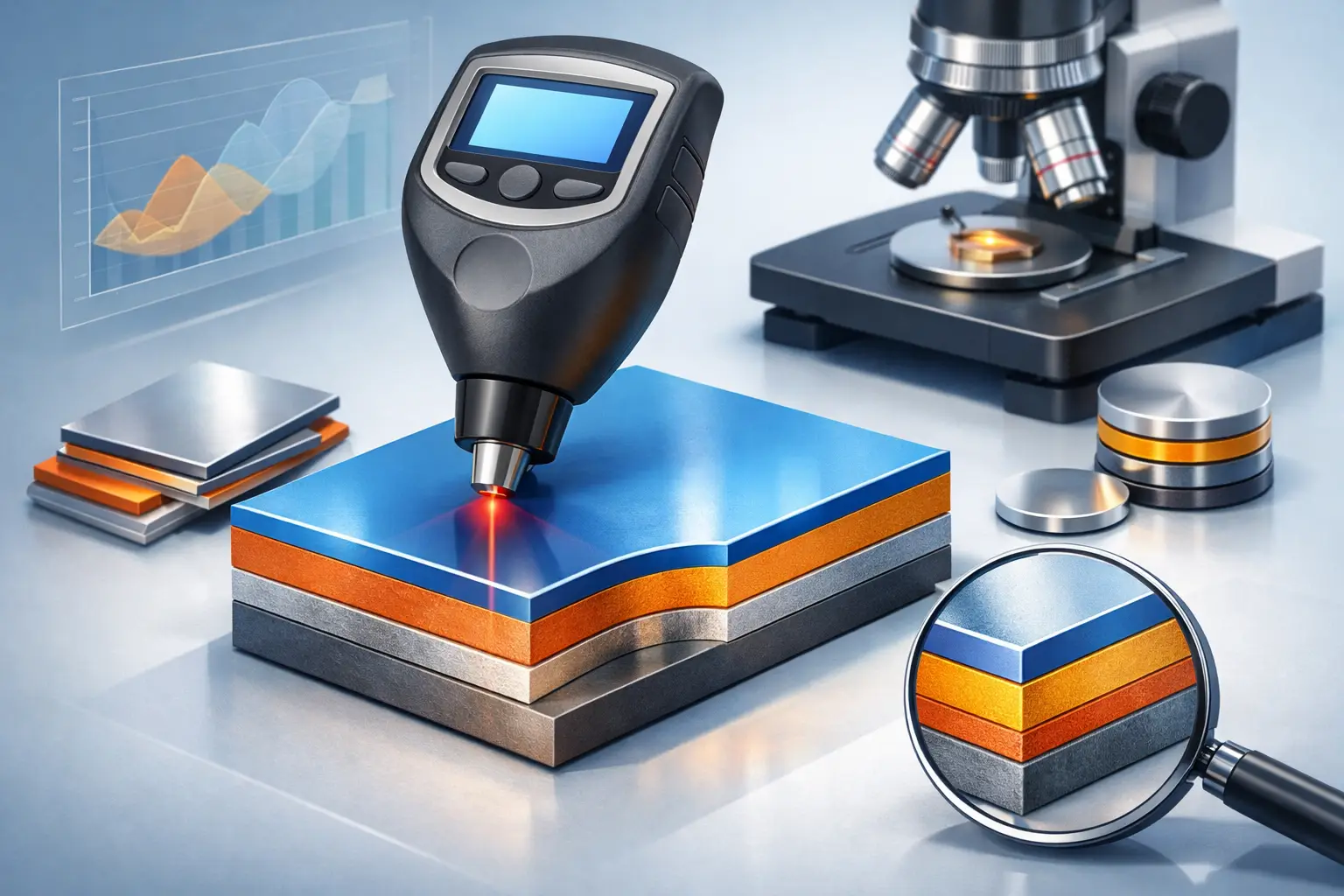
A coating specified at 10 µm is not necessarily a coating delivering 10 µm of protection. On a sharp edge, inside a bore or across a complex assembled component, the local layer thickness may differ significantly from the nominal process value. For regulated and high-reliability applications, a coating thickness measurement guide must therefore address more than the gauge itself. It must connect the measurement principle, component geometry, substrate, coating system and acceptance criterion.
For Parylene, plasma-deposited layers and PVD or CVD thin films, thickness is a functional parameter. It influences barrier performance, dielectric strength, friction, biocompatibility, optical behaviour and dimensional fit. Reliable verification begins by defining what must be measured, where it must be measured and which uncertainty is acceptable.
Why coating thickness is a functional requirement
Thickness requirements are often stated as a single nominal value with a tolerance. That is a useful starting point, but rarely sufficient for demanding components. A corrosion barrier may require a defined minimum thickness at an exposed edge. An electrical insulation layer may need a minimum dielectric distance across a high-field region. A moving precision part may instead have a strict maximum thickness because clearance, friction or fit is critical.
The relevant value can therefore be the local thickness, the minimum thickness over a functional area, the average thickness across a batch or the thickness distribution on selected geometries. These are different measurands. Confusing them creates avoidable disputes between development, production and quality assurance.
Conformal coatings illustrate the point clearly. Parylene can coat external surfaces, internal channels and complex three-dimensional geometries with exceptional conformity. However, conformity does not mean that every location receives precisely the same thickness. Chamber loading, line-of-sight effects in partially shielded areas, component orientation and vapour transport all influence the local result. The measurement strategy must reflect those realities.
Coating thickness measurement guide: start with the application
Method selection should not begin with the available instrument. It should begin with a short technical profile of the coated part. The substrate material, coating composition, expected thickness range, component geometry and permitted test intervention determine which methods are viable.
A magnetic induction gauge is effective for non-magnetic coatings on ferromagnetic substrates. Eddy-current methods are suited to electrically non-conductive coatings on conductive, non-ferrous substrates. Both are fast and practical for production control, but their suitability is limited by the coating-substrate combination. They are not universal thin-film measurement tools, and they can be unreliable on small radii, rough surfaces, curved parts or multilayer structures unless the system has been validated for the specific application.
For metallic thin films on suitable substrates, X-ray fluorescence can provide non-destructive thickness data and, in some cases, compositional information. It is particularly valuable where a PVD layer must meet a narrow functional window. Its limitations include measurement spot size, material combinations, access to the test area and the need for application-specific calibration.
Where no non-destructive electromagnetic method is appropriate, optical or destructive reference methods may be required. A stylus profilometer can measure a defined step between coated and uncoated areas. This is highly informative on test coupons or deliberately masked witness areas, but it does not directly describe thickness on an intact complex component. Cross-sectional microscopy, often using polished sections and scanning electron microscopy, provides direct evidence of layer architecture, interfaces and local thickness. It is among the most persuasive methods for failure analysis and process qualification, although it is destructive and requires careful sample preparation.
Ellipsometry is highly sensitive for very thin, smooth and optically suitable films. It can be an excellent development tool for nanometre-scale layers, but interpretation depends on an appropriate optical model. A result is only as credible as the assumptions used for refractive index, surface roughness and multilayer structure.
Match the method to the thickness range
No single method covers every useful thickness range with equal confidence. The thinner the layer, the more strongly substrate effects, surface roughness and instrument resolution influence the result. A method suitable for a 50 µm polymer coating may not resolve a 100 nm functional layer. Conversely, a high-resolution optical technique may be unnecessarily sensitive and inefficient for a thicker protective coating.
For process development, it is often sensible to combine methods. In-situ monitoring, such as quartz crystal microbalance data, can track deposition behaviour and support process repeatability. It does not automatically replace component-level verification, particularly where geometry affects deposition. Witness coupons, placed at representative positions in the chamber, help establish the relationship between process data and actual coating thickness. Periodic component measurements then confirm that this relationship remains valid.
The trade-off is clear: more measurement points and more sophisticated analysis improve confidence, but they increase cycle time and cost. The right approach is risk-based. A medical component with a critical insulation function warrants a different verification plan from a decorative or non-critical industrial surface.
Define measurement locations before qualification
Thickness data has little value if the measurement locations are arbitrary. Drawings, control plans and inspection instructions should identify functional zones and explain why they matter. Typical critical areas include edges, recesses, internal diameters, contact points, sealing surfaces and regions exposed to chemicals, wear or electrical stress.
For components with complex geometry, a measurement plan should cover both favourable and unfavourable deposition positions. Measuring only an open, accessible face can produce reassuring numbers while leaving the most demanding area unverified. Where direct measurement is impossible, representative witness geometries or sectioned qualification samples may be necessary.
The same principle applies to batch loading. A centrally positioned component may not represent parts near the chamber wall, at the top of a fixture or behind a larger component. Qualification should establish whether the loading configuration creates meaningful variation. Once understood, this variation can be controlled through fixture design, loading rules and defined process windows.
Calibration is not a formality
A thickness gauge can be calibrated and still be unsuitable for the part under test. Calibration standards must resemble the real substrate and coating system as closely as possible. Surface curvature, substrate thickness, magnetic properties, electrical conductivity and roughness can all affect the reading.
This is especially relevant for thin films on technical alloys, polished medical components or roughened mechanical surfaces. A calibration performed on a flat reference panel may not transfer to a narrow cylindrical component. When measurement uncertainty is a significant proportion of the specified tolerance, the resulting pass or fail decision is weak even if the gauge is functioning correctly.
A credible system includes traceable reference standards, documented calibration intervals, verification before use and clear rules for damaged or contaminated probes. For critical programmes, a measurement system analysis should quantify repeatability and reproducibility. If two operators, instruments or test locations generate materially different outcomes, the inspection method needs refinement before it is used for release decisions.
Separate process control from final verification
Process control measurements help operators recognise drift early. Final verification demonstrates that released parts meet the defined requirement. These objectives overlap, but they should not be treated as identical.
For example, a deposition process may be controlled through chamber parameters, source material consumption, deposition time and witness coupon results. Final verification may use sampled component measurements, cross-sections from qualification parts or a validated non-destructive technique. The appropriate sampling level depends on process capability, component risk and the consequences of an undetected thin area.
For established, capable processes, reduced inspection can be justified by historical data. For a new geometry, changed substrate, revised masking concept or new chamber loading, increased verification is prudent. Changes that appear minor from a production perspective can alter local coating thickness in ways that matter functionally.
Common sources of misleading thickness data
The most frequent errors are not instrument failures. They are failures of definition and preparation. Measuring over dirt, fingerprints or condensation can alter a reading. Surface roughness may be interpreted as coating variation. Measuring too close to an edge can exceed the probe’s valid geometry range. A multilayer stack can be reported as one layer when the functional requirement applies only to the top layer.
Another common issue is reporting an average where the specification requires a minimum. A batch may achieve the target mean thickness while individual critical areas fall below the protective threshold. Conversely, a local high reading can lead to rejection even though it is outside the functional zone and does not impair performance. Inspection criteria should distinguish between these cases.
Build thickness verification into the coating programme
Thickness measurement is most effective when considered during component and process development, rather than added shortly before serial release. Early discussion can identify measurable reference areas, suitable witness coupons, fixture concepts and acceptance limits that reflect the actual function of the coating.
For technically demanding programmes, NTTF Coatings combines application-specific process development with measurement concepts suited to the coating technology, part geometry and quality requirements. This approach supports reproducible protection and performance rather than a nominal value that cannot be meaningfully verified.
The useful question is not simply, “What thickness did we measure?” It is, “Can we demonstrate that the functional areas of this component received the coating required for reliable service?” A well-designed measurement plan gives engineering, quality and production the same defensible answer.
